I/p Converter Circuit Diagram [diagram] Schematic Circuit Di
What is an i/p converter? working principle, applications- electrical volt Compact current i/p to pressure converter with high accuracy Circuit diagram of the i-v converter.
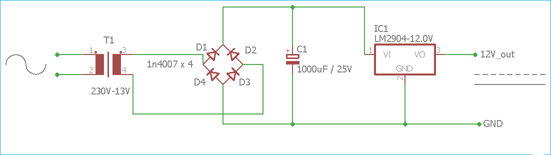
12v Dc Mobile Charger Circuit Diagram
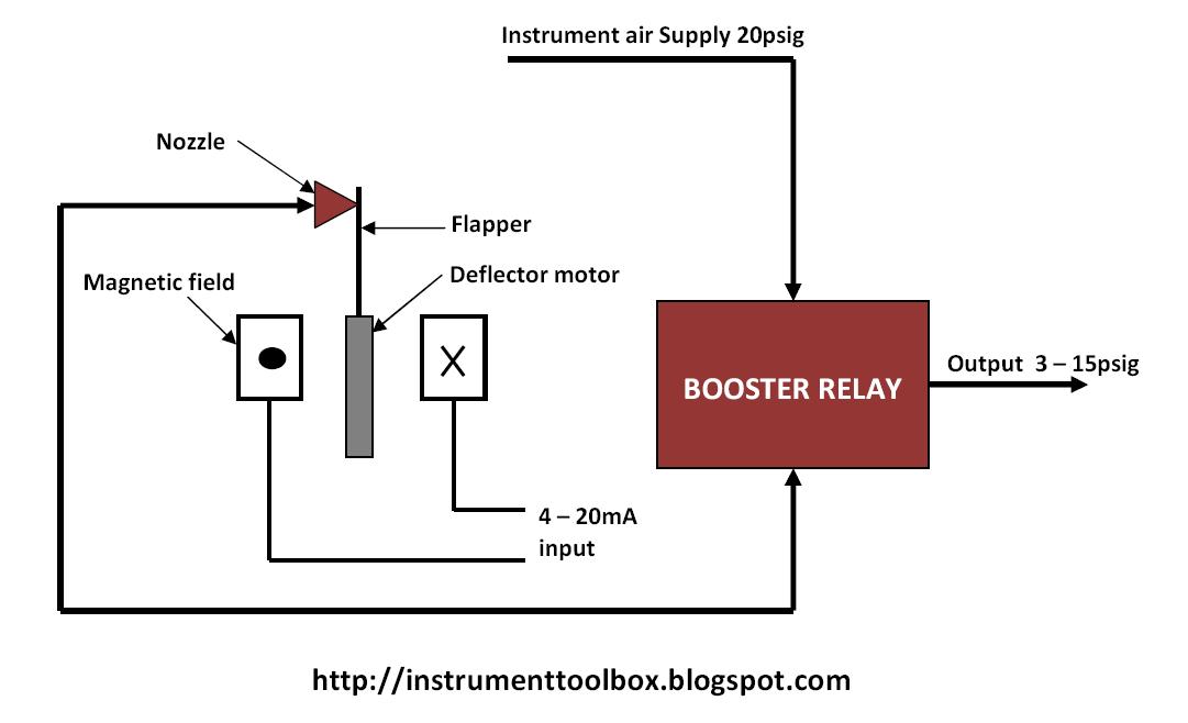
1.5v to 5v boost converter circuit for micro computer What is an i/p converter? working principle, applications- electrical volt 4: arrangement for i-p conversion
Circuit diagram of the i-v converter.
Vlf converter circuit diagram simple schematicsDetailed circuit diagram of the integrated converter. Calibration of i/p converterVlf converter circuit diagram.
I/p converter calibrationConverter diagram lab tech panel front Converter and its peripheral circuit diagram.Circuit diagram of the proposed converter..

I/p converter
Circuit schematic diagram of the proposed converterCircuit diagram of the converter. Circuit diagram of the converter.Converter current.
Converter circuitCircuit diagram of the proposed converter 220v to 12v dc converter circuit diagramTech lab: i/p and p/i converter.

Circuit diagram of the proposed integrated converter
4-20ma abb i to p converter, for control valve operating at rs 1150Current to pressure (i/p) converter calibration procedure Converter 5v micro circuit boost dc step computer eleccircuit 12v battery voltage diagram circuits power output electronic convert charger 2vCircuit diagram of the proposed integrated converter.
[diagram] i p converter circuit diagram[diagram] schematic circuit diagrams components Transducer pressure current converter principle control instrumentation ip engineering 20ma works input output shown operating learningIp converter.
Circuit diagram of the proposed converter
Circuit diagram of i/v converter and instrumentation amplifierHow a current to pressure transducer (i/p) works ~ learning Calibration of i/p converterCurrent to pressure (i/p) converter principle chemical engineering.
What is an i/p converter? working principle, applications- electrical voltI/p converter |current to pneumatic signal converter |working & it's 12v dc mobile charger circuit diagram.


