Hydraulic Valve Circuit Diagram Mariners Repository: Hydraul
Double-pump hydraulic system Marinah: [16+] double acting hydraulic pump wiring diagram, patent The real value of hydraulic circuit diagrams
Basic Components and its Functions of a Hydraulic System
What is a hydraulic system? definition, design, and components Hydraulic schematic cylinder circuit control diagrams drawings read fluids diagram valve drawing symbols hydraulics examples report wiring assembly reading [diagram] 3 position valve diagram
Basic hydraulic system circuit diagram
How a hydraulic self-leveling valve worksValve hydraulic leveling self articles lefebure parts circuit works through Basic components and its functions of a hydraulic systemElectro system actuation.
Hydraulic circuit diagram// 4 way 3 position directional control valveServovalve, hydraulic Flow control valves hydraulic symbology 204Mariners repository: hydraulics part 1.

Hydraulic valve symbols
The basics of hydraulic circuitryHydraulic components functions its syste Hydraulic symbols control pneumatic[diagram] drip system diagram.
Understanding a basic hydraulic circuit 01Hydraulic valve proportional eh ceva Hydraulic valve leveling self lefebure parts drawing articlesHow to read hydraulic schematic drawings.

Hydraulic schematic system figure
Digital hydraulic schematic diagram of working device of loaderHydraulic valve control directional inchbyinch Details of an eh-ceva: (a) proportional hydraulic valve module; (bHydraulic circuit drawing diagrams real power fluid drawings journal.
Hydraulic circuit system components systems circuits flow definition using works linear elements discrete training pumpsHydraulic symbols system drawing circuit engineering diagram pump mechanical simple beginners electrical cylinder fluid solenoid valve basic controlled valves flow Hydraulic circuit diagram diagrams graphical value figure hyd read true[diagram] hydraulic flow control valve diagram.
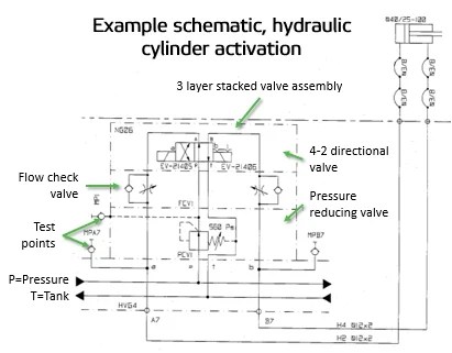
Schematic of the electro-hydraulic valve actuation system.
How a hydraulic self-leveling valve worksHydraulic valves spool directional monoblock gpm hydraulics magisterhyd rod rebuild magister bore tang stroke sleeve kubota Solenoid diverter 12v selector valves hydraulicsHydraulic system schematic.
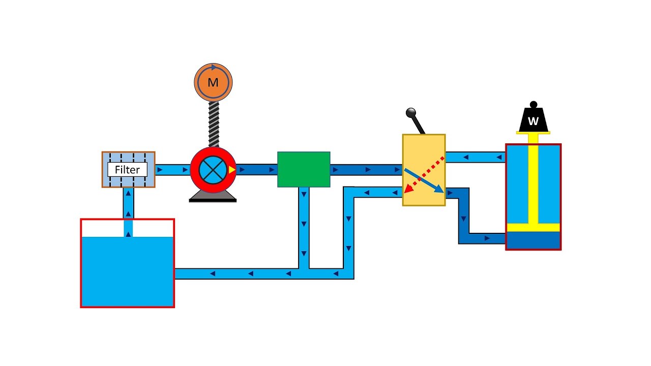
Way valves two valve spool control three flow four direction ports pressure rotary drawing port hydraulics machine other partHydraulics systems diagrams and formulas Hydraulic pump system double schematic cylinder circuits industrial dcv spring troubleshooting operation[5+] what is hydraulic circuit diagram, hydraulics principles and.

Basic hydraulic circuit diagram pdf
Hydraulic valve circuit diagramHydraulic system for beginners Valve hydraulic control diagram directional way circuit position basicControl direction way valves four hydraulics methods drawing actuation part.
2 spool x 11 gpm hydraulic control valve, monoblock cast iron valveHydraulic loader hydraulics formulas terminology deere spool tractors pto mfg The true value of hydraulic circuit diagramsMachine drawing: rotary four way valves.
How to draw hydraulic circuit diagram
Wiring diagram for hydraulic solenoidHydraulic basics training circuitry pump Hydraulic servo valves servovalve anslagstavla välj.
.


![[5+] What Is Hydraulic Circuit Diagram, Hydraulics Principles And](https://i.ytimg.com/vi/KCE-TS5A0GM/maxresdefault.jpg)

![[DIAGRAM] Hydraulic Flow Control Valve Diagram - MYDIAGRAM.ONLINE](https://i2.wp.com/insights.globalspec.com/images/assets/786/12786/Pressure-compensated_Flow_Control_Valve_Diagram.png)
